Thickness, Parallelism and Flatness

Thickness, Parallelism and Flatness. How do they relate?

Thickness, parallelism and flatness are related terms that are especially important with regards to plate dimensions.  But how do they relate? How are they different? We hope to offer here some standardized definitions and explanations for thickness, parallelism and flatness.

Below is an example of a plate description:

2.50″ x 24.00” x 36.00”, A36, rectangle, flame cut and cleaned, stress relieved, Blanchard ground to 2.304” (+/-0.010”), flat within 0.005” per foot, parallel within 0.005”.

Thickness description: 2.50″ is the nominal plate thickness that the part will be cut from. The dimension 2.304” (+/-0.010”) is the finish thickness with the maximum allowable thickness being 2.314″ and the minimum allowable thickness being 2.294″

Flatness description: flat within 0.005” per foot

Parallelism description: parallel within 0.005”

Thickness, Parallelism and Flatness – Definitions

Plate thickness: the distance between two surfaces of a part (commonly the top and bottom) with a deviation tolerance specified (ex. 2.307” +/-0.0010”).  This distance is most commonly measured by using precision micrometers.

Plate parallelism: parallelism is related to thickness. The difference between the thickest and thinnest points on a plate (ex. 2.307″ thickest measurement, 2.302″ thinnest measurement = parallel within 0.005″)

Plate flatness: Flatness is not related to thickness or parallelism! Plate flatness is measured relative to a reference surface such as a grinder table or granite table. Flatness is most commonly measured as a deviation per linear foot from the reference plane.

One example of measuring flatness: A part is place on three reference blocks resting on a granite table.  A precision indicator is then passed underneath the part measuring the distance between the surface of the granite table and the bottom surface of the part.  Indicator readings are taken at various locations on the bottom surface of the part.  The total variation of the indicator readings is the total flatness, also known as the T.I.R. (Total Indicator Runout).

Some drawings ask for a part to be flat in the restrained condition. This is not true flatness but the surface is intended to be flat enough to be bolted or clamped in a flat condition.

Normally, if a flatness of 0.003″/ft. is quoted, then multiply the diagonal dimension of the part in feet by 0.003″ to get the total flatness tolerance. See example illustrations below.

Illustrations

Thickness and Parallelism
Flatness


Plate Description Variations

2.50” x 24.00” x 36.00”, A36, Flame cut and cleaned, stress relieved, Blanchard ground to 2.250” (+/-0.010”), flat and parallel

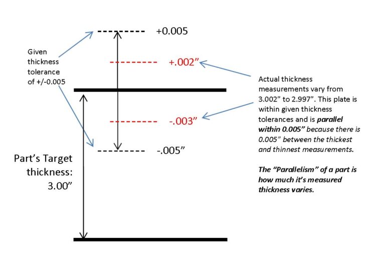
Sometimes the term “flat and parallel” is used in the part description without numerical values.  In this case, techniques will be used during the grinding process to improve a part’s flatness and parallelism while obtaining the specified thickness.  However,  particular flatness and parallelism values are not guaranteed.

2.50” x 24.00” x 36.00”, A36, Flame cut and cleaned, stress relieved, Blanchard ground to 2.250” (+/-0.010”)

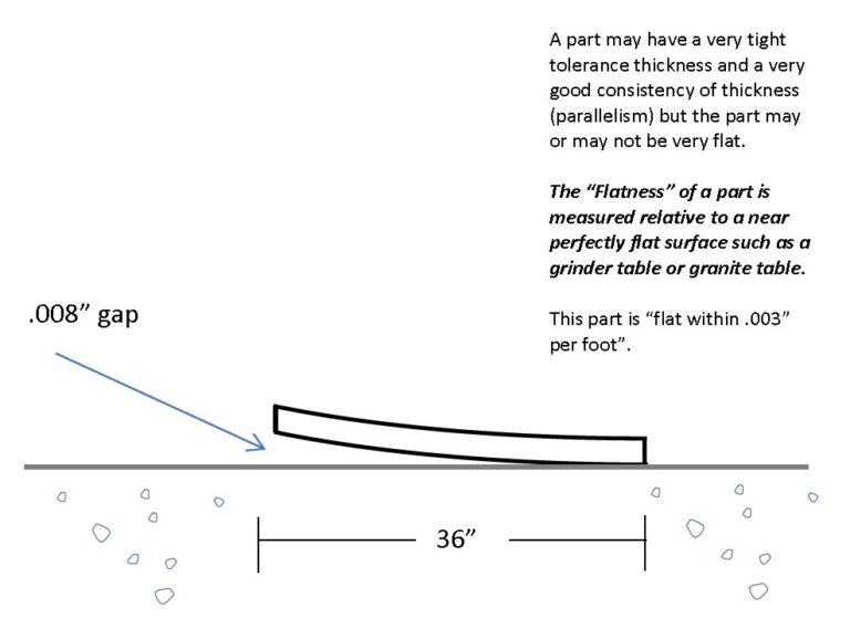
When the part will be bolted or welded to another surface, flatness is not as important to specify.  Sometimes there is no mention of flatness and parallelism in a part description.  In such cases, techniques to improve the natural flatness of the part may not be used making the part more economical.


REQUEST A QUOTE